

Structure of a Pepperl+Fuchs Type Code
For Inductive, Capacitive, Magnetic Field, and Ultrasonic Sensors
Pepperl+Fuchs’ product portfolio consists of several thousand sensors with different operating principles and offers the ideal solution for almost every application. These details and more are reflected in our order number, the Pepperl+Fuchs type code.
The type code is made up of three sections (seprerated by hyphens), each of which refers to specific product features. Below, we will explain and provide examples for how this is composed for inductive, capacitive, magnetic field, and ultrasonic sensors.
- The first section (NCN15) contains information on operating principle (sensor type), series-specific application features (type of application), installation situation (flush/non-flush), and switching distance.
-
The second section (30GS60) provides the size of the thread, design, material, thread length, and transducer type (option 1, angled/swiveling).
-
The third section (E2-V1) describes the electrical outputs, special characteristics (e.g., whether the output is flameproof or weld spatter resistant), option 2 (e.g., whether the sensor is IO-Link-capable), and connections.
Structure of our type code using the example of an inductive sensor
N
 N = inductive sensor
Inductive sensors detect metal objects and are used in many applications, e.g. in spraying lines or component recognition in the automotive industry.
C
C = comfort range
N
 N = non-flush Non-flush sensors can be replaced with flush sensors, but not the other way round.
15
15 = 15 mm switching distance The minimum distance must be observed, otherwise the sound will reach the sensor too quickly and the reaction time will be too low. This blind distance must be avoided.
N = non-flush Non-flush sensors can be replaced with flush sensors, but not the other way round.
15
15 = 15 mm switching distance The minimum distance must be observed, otherwise the sound will reach the sensor too quickly and the reaction time will be too low. This blind distance must be avoided.
-
30 30 = 30 mm big thread
G G = thread
S S = stainless steel
60 60 = 60 mm usable thread length
-
E2 E2 = three-wire, DC, PNP, no contact
-
V1 V1 = M12 x 1 device plug for DC sensors
Description of the First Section
1. Operating principle
All Pepperl+Fuchs sensors are listed under the category "functional principle," where the first letter of the type code symbolizes a defined sensor type. For example, the letter “U” stands for “ultrasonic sensor” and the letter “N” for “inductive sensor.”
2. Series-specific application features
When selecting a sensor, it is important to determine where and how the sensor will be used. Under the category "application-specific features," you will find the different application areas of sensors with their type descriptions. For example, the UC6000 ultrasonic sensor can be used for water rides, since neither dirt nor water impairs the function of the comfort series (C).
3. Installation situation
Inductive sensors measure switching distances by generating an electromagnetic field and using changes in the magnetic field to determine whether an object is in the sensor’s detection range. Metallic components around a sensor weaken the magnetic field and thus the sensor’s range.
Flush mount sensors can be used without free space (area=0). This gives flush mount sensors an advantage because they have better mechanical protection and are less susceptible to interference than non-flush mount sensors. However, flush mount sensors only achieve around 60% of the switching distance of non-flush versions because the active surface of the sensor is already surrounded by metal. Special internal shielding reduces the lateral influence of the surrounding metal but this affects range.
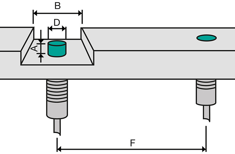
Installation Situation (flush mount / non-flush mount)
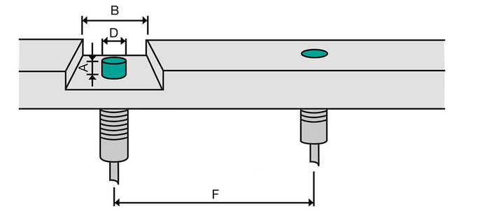
- A = 2 x switching distance
- B = 3 x diameter
- D = sensor diameter
- F = distance between sensors
4. Switching distance
The switching distance is the most important parameter of a proximity switch and depends mainly on sensor size (coil or capacitor). The dimensions and material composition of the actuator, as well as the ambient temperature, also have an influence. With magnetic proximity switches, the alignment and strength of the magnet used must also be taken into account.


Pepperl+Fuchs S.A.
Metropoolstraat 11
2900 Schoten / Anvers
Belgique
TVA BE 0436.097.152, RPM Anvers, dép.Anvers
sales@be.pepperl-fuchs.com
 +32 3 644 25 00
Pepperl+Fuchs est leader comme concepteur et fabricant de capteurs et composants électroniques pour le marché mondial de l'automatisation. L'innovation constante, la qualité incontestable et la croissance soutenue, garantissent notre succès, depuis plus de 70 ans. Pepperl+Fuchs emploie 6300 personnes dans le monde et compte des usines en Allemagne, aux USA, à Singapour, en Hongrie, en Indonésie et au Vietnam ; la plupart d'entre elles sont certifiées ISO 9001.