

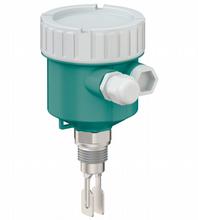
Vibration Limit Switch Compact Version LVL-M3-A
- Vibration limit switch for liquids
- Compact device
- Wide variety of electronic modules (e. g., relay, thyristor signal output): the right connection for every process control system
- No calibration: quick and low-cost start up
- No mechanically moving parts: maintenance-free, no wear, long operating life
- Operation via push buttons and DIP switches on the electronic insert


Please note: All product-related documents, such as certificates, declarations of conformity, etc., which were issued prior to the conversion under the name Pepperl+Fuchs GmbH or Pepperl+Fuchs AG, also apply to Pepperl+Fuchs SE.
Téléchargez ici la fiche technique complète en PDF:
Caractéristiques techniques LVL-M3-A
| General specifications | ||
|---|---|---|
| Function principle | point level detection, maximum or minimum detection for liquids | |
| Measuring method | The change in vibration frequency causes the device to switch. | |
| Construction type | compact device | |
| Series | Vibracon LVL-M3 | |
| Housing | single compartment, aluminum, coated single compartment, plastic |
|
| Supply | ||
| Rated voltage | electronic insert FEL42: 10 V DC ... 55 V DC electronic insert FEL44: 19 V AC ... 253 V AC/19 V DC ... 55 V DC electronic insert FEL48: switch amplifier acc. to IEC 60947-5-6 (NAMUR) |
|
| Current consumption | electronic insert FEL42: ≤ 10 mA, without load | |
| Power consumption | electronic insert FEL42: ≤ 0,5 W electronic insert FEL44: ≤ 25 VA/< 1.3 W electronic insert FEL48: acc. to IEC 60947-5-6 (NAMUR) |
|
| Input | ||
| Switching point | see section switch point | |
| Measured variable | limit level (limit value) | |
| Measurement range | depends on installation location and the tube extension maxmum sensor length : 2 m |
|
| Output | ||
| Output type | electronic insert FEL42: 3-wire PNP electronic insert FEL44: relay DPDT electronic insert FEL48: 2-wire NAMUR |
|
| Switch behaviour | switch-over for minimum/maximum residual current safety on electronic insert MAX = maximum safety: The output switches to the power fail response when the fork is covered. for use with overspill protection for example MIN = minimum safety: The output switches to the power fail response when the fork is exposed. for use with dry running protection for example |
|
| Directive conformity | ||
| Electromagnetic compatibility | ||
| Directive 2014/30/EU | EN 61326 | |
| Low voltage | ||
| Directive 2014/35/EU | EN 61010-1 | |
| Conformity | ||
| Electromagnetic compatibility | NE 21 | |
| Degree of protection | IEC 60529 , NEMA 250 | |
| Shock resistance | IEC 60068-2-27 | |
| Vibration resistance | EN 60068-2-64 | |
| Climate class | IEC 60068-2-38 test Z/AD | |
| Corrosion resistance | acc. to ISA-71.04, severity level G3 | |
| Input characteristics | ||
| Medium density | adjustment on the electronic insert > 0,5 g/cm3 or > 0,7 g/cm3 (other on request) | |
| Measurement accuracy | ||
| Reference operating conditions | ambient temperature: 23 °C (73 °F) process temperature: 23 °C (73 °F) density: 1 g/cm3 (water) medium viscosity: 1 mPa·s process pressure: ambietn pressure/unpressurized sensor installation: verticaly from above density selection switch: > 0.7 g/cm3 switch direction of sensor: uncovered to covered |
|
| Maximum measured error | max. ± 1 mm | |
| Hysteresis | typ. 2.5 mm | |
| Influence of medium density | see technical information (TI) | |
| Influence of medium temperature | max. +1.4 ... -2.8 mm (-40 ... 150 °C (-40 ... 302 °F)) | |
| Influence of medium pressure | max. 0 ... 2.6 mm (-1 ... 40 bar) | |
| Operating conditions | ||
| Installation conditions | ||
| Installation position | any position | |
| Process conditions | ||
| Medium temperature | -40 ... 150 °C (-40 ... 302 °F) | |
| Medium pressure | pe = -1 ... 40 bar (-14.5 ... 580.2 psi) over the entire temperature range , exceptions see process connections | |
| Test pressure | PN = 40 bar (580 psi): test pressure = 1.5 x PN max. 60 bar (870 psi) dependent on the process connection selected | |
| Thermal shock resistance | ≤ 120 K/s | |
| State of aggregation | liquid | |
| Density | min. 0.5 g/cm3 , optional 0.4 g/cm3 | |
| Viscosity | max. 10000 mm2/s (max. 10000 cSt) | |
| Ambient conditions | ||
| Ambient temperature | -40 ... 70 °C (-40 ... 158 °F) For further information see technical information (TI). |
|
| Storage temperature | -40 ... 80 °C (-40 ... 176 °F) | |
| Altitude | ≤ 2000 m above MSL | |
| Mechanical specifications | ||
| Degree of protection | plug M12 : IP66/67, NEMA type 4X Others : IP66/68, NEMA type 4X/6P |
|
| Connection | gland M20 thread M20 , G1/2 , NPT1/2 , NPT3/4 plug M12 |
|
| Material | see technical information (TI) | |
| Surface quality | Ra < 3.2 µm/126 µinch | |
| Mass | basic weight: 0.65 kg the basic weight comprises: - sensor (compact) - electronic insert - housing: single compartment, plastic with cover - process connection: thread, G3/4 in addition to the basic weight: - housing: single compartment, aluminum, coated: 0.8 kg - pipe extension: 1000 mm: 0.9 kg, 100 inch: 2.3 kg - plastic protective cover: 0.2 kg For further information see technical information (TI). |
|
| Dimensions | housing: diameter max. 101 mm, heigth max. 118 mm compact version: length depends on process connection short tube version: length 99 ... 118 mm, depends on process connection tube extension: length 117 ... 2000 mm tuning fork: width 17.2 mm, fork width 10 mm, length 40 mm For further information see technical information (TI). |
|
| Process connection | cylindrical threads G3/4, G1 acc. to DIN ISO 228 G for installing in weld-in adapter cylindrical threads G3/4, G1 acc. to DIN ISO 228 G with flat seal conical threads NPT3/4, NPT1 acc. to ANSI B 1.20.3 conical threads R3/4, R1 acc. to EN 10226 flanges RF, RJF, FF from 1 inch acc. to ASME B16.5 flanges form A, B1, C, D, E from DN25 acc. to EN 1092-1 flanges RF from 10K 25A acc. to JIS B2220 Tri-Clamp from DN25 acc. to ISO 2852 For further information see technical information (TI). |
|
| Data for application in connection with hazardous areas | ||
| EU-type examination certificate | see instruction manuals | |
| International approvals | ||
| CSA approval | see instruction manuals | |
| IECEx approval | see instruction manuals | |
| Indication and operation | ||
| Display elements | without display | |
| Control elements | switches on the electronic insert | |
| Function test | via switches on the electronic insert | |
| Certificates and approvals | ||
| Overspill protection | see approval (ZE) | |
| General information | ||
| Supplementary documentation | technical information (TI) manuals, brief instructions (BA, KA) instruction manuals Special documentation (SD) |
|
| Supplementary information | Observe the certificates, declarations of conformity, instruction manuals, and manuals where applicable. For information see www.pepperl-fuchs.com. | |
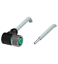
| Accessories | ||
| Designation | see technical information (TI) | |
Classifications
| System | Classcode |
|---|---|
| ECLASS 13.0 | 27200518 |
| ECLASS 12.0 | 27200518 |
| ECLASS 11.0 | 27200518 |
| ECLASS 10.0.1 | 27200518 |
| ECLASS 9.0 | 27200589 |
| ECLASS 8.0 | 27200589 |
| ECLASS 5.1 | 27200589 |
| ETIM 9.0 | EC001447 |
| ETIM 8.0 | EC001447 |
| ETIM 7.0 | EC001447 |
| ETIM 6.0 | EC001447 |
| ETIM 5.0 | EC001447 |
| UNSPSC 12.1 | 41111950 |
Details: LVL-M3-A
Product Documentation: LVL-M3-A
| Product information | Langue | Type de fichier | Taille |
|---|---|---|---|
| Technical information | ENG | 2749 KB | |
| Brief Instructions | |||
| Brief instructions | ENG | 2483 KB | |
| Safety and Security Documentation | |||
| Manuel d'instructions | FRA | 174 KB | |
| Manuel d'instructions | FRA | 170 KB | |
| Manuel d'instructions | FRA | 173 KB | |
| Manuel d'instructions | FRA | 170 KB | |
| Manuel d'instructions | FRA | 172 KB | |
| Temperature tables for CC approval | ENG | 2001 KB | |
| Temperature tables for CH approval | ENG | 1984 KB | |
| Temperature tables for CX approval | ENG | 2006 KB | |
| Temperature tables for E2 approval | ENG | 1986 KB | |
| Temperature tables for E3 approval | ENG | 2007 KB | |
| Manuals | |||
| Manual | ENG | 2713 KB | |
Design / Simulation: LVL-M3-A
| CAD | Langue | Type de fichier | Taille |
|---|---|---|---|
| CAD 3-D / CAD 3-D | ALL | STP | 560 KB |
Approvals: LVL-M3-A
| Contamination Declaration | Identification | Langue | Type de fichier | Taille |
|---|---|---|---|---|
| Contamination declaration / Kontaminationserklärung | ALL | 137 KB |
Produits associés : LVL-M3-A
| Accessories | ||||||
|---|---|---|---|---|---|---|
|
||||||


Plusieurs centaines de produits ayant fait l'objet d'une évaluation SIL/PL, des outils gratuits et des brochures au même endroit : le « Centre de sécurité fonctionnelle » est votre point de départ lorsque vous devez mettre en œuvre des fonctions de sécurité.


Pepperl+Fuchs S.A.
Metropoolstraat 11
2900 Schoten / Anvers
Belgique
TVA BE 0436.097.152, RPM Anvers, dép.Anvers
sales@be.pepperl-fuchs.com
 +32 3 644 25 00
Pepperl+Fuchs est leader comme concepteur et fabricant de capteurs et composants électroniques pour le marché mondial de l'automatisation. L'innovation constante, la qualité incontestable et la croissance soutenue, garantissent notre succès, depuis plus de 70 ans. Pepperl+Fuchs emploie 6300 personnes dans le monde et compte des usines en Allemagne, aux USA, à Singapour, en Hongrie, en Indonésie et au Vietnam ; la plupart d'entre elles sont certifiées ISO 9001.