

Available Types of Output
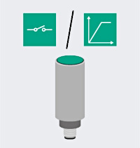
Each sensor output type provides information as to whether it is a binary (switching) sensor with two defined states, analog output values, or a data-transferring (measuring) sensor. Below you will learn about the types of output for which inductive sensors are available and how these outputs work.
Switching Sensors
Note: You can find information on the electrical connection of different sensors according to their types of output under Sensor Connection.
Traditional inductive proximity sensors, i.e., simple on/off switches, are included in this range. They can switch between two defined states and thus control actuators such as valves, flaps, signal lights, etc. Inductive proximity sensors can be connected to digital inputs of programmable logic controllers.
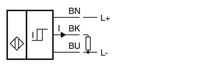
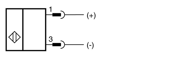
1. Sensor with NPN Output (Signal "Negative")
An NPN output of the sensor connects the output connection to ground when switched. The load is connected between the supply voltage +UB and the sensor's NPN output.
Example of a sensor with NPN output
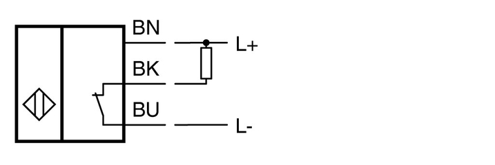
2. Sensor with PNP Output (Signal "Positive")
A PNP output of the sensor connects the output connection to the supply voltage of the sensor when switched. The load is connected between the PNP output of the sensor and ground L-.
Note: Sensors with PNP output tend to be used more frequently to prevent short circuits to ground.

Example of a sensor with PNP output
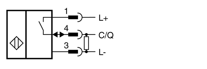
3. Sensor with Two-Wire Function
Inductive sensors with two-wire function use this common type of output with only two output cables for power supply and signal transmission.
The sensor is operated in series to the connected load. In a series connection, the order in which the sensor and load are arranged is irrelevant.

Example of a sensor with two-wire function
How It Works
A sensor with two-wire function is an active component that requires energy to function. The sensor is supplied with this electrical energy via the two connecting wires. At the same time, the sensor signals its switch state via the same connecting wires.
A sensor with two-wire function is often equated with a mechanical switch in terms of how it works. Nevertheless, this type of sensor works differently than a mechanical switch, which is open or closed depending on the sensor's damping situation. No current flows through an open mechanical switch. The connected load is not energized. Conversely, in an ideal situation, voltage does not drop via a closed mechanical switch. The entire supply voltage is applied across the load.
In contrast, a sensor with two-wire function—as an active component—requires voltage and current at all times. Even in the closed state, a non-negligible voltage, missing from the connected load, drops across the sensor. When open, a current flows through the sensor and the connected load. When operating a sensor with two-wire function, the unique states "open" and "closed" therefore never exist.
Sensors with two-wire function are mostly operated at digital inputs of a programmable logic controller (PLC). Depending on their type, these digital inputs have an input impedance according to EN 61131-2. This must be taken into account when selecting the sensor with two-wire function. Pepperl+Fuchs standard sensors with two-wire function can be operated at type 2 digital inputs. Type 3 digital inputs require a low residual current. Sensors with two-wire function with Z4L (or Z8L) output stages are suitable for operation at type 3 digital inputs.
Occasionally, sensors with two-wire function are operated on discrete loads. The individual resistance value of the load must be taken into account. The technical data for sensors with two-wire function does not provide any direct information on this, since the resistance value depends on the operating voltage of the plant and the minimum and maximum operating current of the sensor.
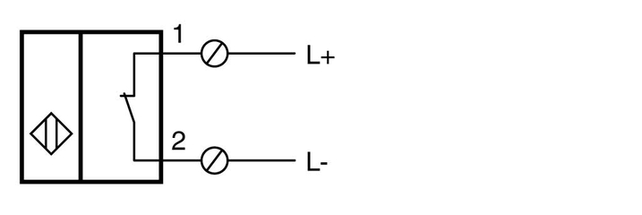
4. Sensor with Relay Contact Output
A sensor with relay contact output has a binary output that controls a relay. Switching is performed via a separate control circuit as opposed to the power circuit as a "controlled" circuit.
Example of a sensor with relay contact output
How It Works
Sensors with relay contact output have at least four connections. Two connections are used to supply the sensor electronics. The remaining connections lead potential-free relay contacts outward. These are two connections with an NC/NO contact and three connections with a changeover contact. Relay contacts are mechanical contacts that usually have a higher current-carrying capacity than electronic switching outputs. For this reason, relay contacts are subject to mechanical wear. The switching frequency is also limited to few switching processes per second. A key feature of a relay contact is its potential-free operation.
5. Sensor with NAMUR Output Signal
A sensor with this type of output generates output signals that correspond to the additional safety function according to the NAMUR specifications, e.g., a suitably designed proximity sensor or a rotary encoder.
Example of a sensor with a NAMUR output signal
How It Works
NAMUR sensors are two-wire sensors that represent the switch state via specific current values as defined in the EN 60947-5-6 standard. NAMUR sensors are usually connected to isolated switch amplifiers that interpret the current values of the NAMUR sensor and convert them into discrete switching outputs. Together with a suitable isolated switch amplifier, NAMUR sensors form an intrinsically safe circuit for use in explosion-hazardous areas. Alongside the switching output control, the isolated switch amplifier provides short-circuit and lead breakage detection.
Two versions:
Traditionally, NAMUR sensors have a constant output characteristic. NAMUR sensors with this output characteristic are marked with "N" in the type designation.
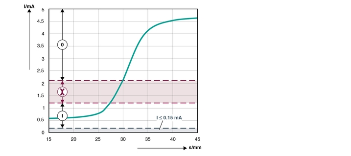
Area 0: unactuated area
Red area between 0/I: impermissible area of the switch amplifier
Area I: actuated range
Area ≤ 0.15 mA: lead breakage
Area ≥ 6.5 mA: short circuit
In addition, Pepperl+Fuchs offers NAMUR sensors with binary switching characteristics. NAMUR sensors with this output characteristic are marked with "N0" (normally-closed characteristics) or "N1" (normally-open characteristics) in the type designation.
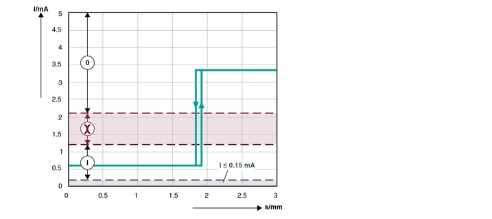
Area 0: unactuated area
Red area between 0/I: impermissible area of the switch amplifier
Area I: actuated range
Area ≤ 0.15 mA: lead breakage
Area ≥ 6.5 mA: short circuit
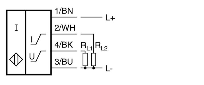
6. Sensor with Digital Current Output
A sensor with digital current output is a conventional, binary inductive sensor. The switching signal is issued in the form of two discrete current values.
Example of a sensor with digital current output
How It Works
Binary inductive sensors are usually used for presence detection. The object detection state is transmitted as a binary signal (switching signal).
Output current 5 mA: no object detected
Output current 10 mA: object detected
Measuring Sensors
Inductive sensors with the following types of output can detect (measure) and transmit multiple signals or status information about the returned current or voltage values.
1. Sensor with Analog Current Output (4 mA … 20 mA)
This type of output relates to an inductive analog sensor that detects a physical variable—e.g., the distance from a metallic object—and provides this measured value converted as an analog current value at the analog output.

Example of a sensor with analog current output
How It Works
Sensors with analog current output can be used for distance measurement between the sensor and damping element.
2. Sensor with Analog Voltage Output (e.g., 0 V … 10 V)
This sensor type is another type of inductive analog sensor that detects a physical variable—e.g., the distance from a metallic object—and provides this measured value converted as an analog voltage value at the analog output.
Example of a sensor with analog voltage output
How It Works
Sensors with analog voltage output can be used for distance measurement between the sensor and damping element.
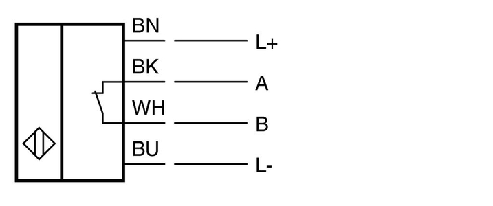
3. Sensor with AS-Interface
Sensor that can be used for industrial fieldbus communication with AS-Interface. The switch state and any other data are transferred via AS-Interface.
Example of a sensor with AS-Interface
How It Works
AS‑Interface is a standard of fieldbus communication at the lower field level for industrial communication. AS-Interface works according to the master/secondary device principle and is used to transmit data and energy on a two-wire line. As a communication standard, it is cost-effective and flexible and is therefore often used in factories and automation systems. The result is that sensors for AS-Interface can be used in many industrial applications with pre-existing AS-Interface structures. The AS-Interface flat cable with piercing technology allows integration into these existing structures quickly and without a great deal of connection effort.
4. IO-Link Sensor
An IO-Link sensor works with input/output signals to provide data on a standardized M8 or M12 plug for intelligent (IO-Link) communication of sensors and actuators at field level.
Example of a sensor with IO-Link
How It Works
IO-Link is a point-to-point connection. A sensor is directly assigned to an IO-Link master. By identifying the sensor and transferring large amounts of data, IO-Link sensors are particularly suited for use in Internet of Things (IoT) applications. IO-Link sensors can be used in the SIO operating mode (SIO = standard input and output). This means that these sensors are suitable in conventional applications without IO-Link communication.
Output Logic
A typical output function of inductive sensors is binary "switching." Based on two different states, different functions are possible. The repeat accuracy and switching hysteresis must be observed.
A second type of inductive sensor provides an analog output function. In this case, a sliding current value of 4 mA … 20 mA or a voltage value of 0 V … 10 V is issued. For the measurement to be successful, central framework conditions, such as resolution, repeat accuracy, switching frequency, and linearity must be observed.


Pepperl+Fuchs AB
Bultgatan 40 A
442 40 Kungälv
Sverige
orgnr. 556212-2126
info@se.pepperl-fuchs.com
 +46 303 246070
Pepperl+Fuchs is a leading developer and manufacturer of electronic sensors and components for the global automation market. Continuous innovation, enduring quality, and steady growth have been the foundation of our success for more than 70 years. Pepperl+Fuchs employs 6,300 people worldwide and has manufacturing facilities in Germany, USA, Singapore, Hungary, Indonesia and Vietnam, most of them ISO 9001 certified.