Línea de servicio de Sensores Industriales
Teléfono: +34 94 453 50 20
Fax: +34 94 453 51 80
Atención al cliente para protección contra explosiones
Teléfono: +34 94 453 50 20
Fax: +34 94 453 51 80
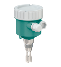
Vibration Limit Switch LVL-M3
- Vibration limit switch for liquids
- Large selection of process connections: universal use
- Wide variety of electronic modules (e. g., relay, thyristor signal output): the right connection for every process control system
- No calibration: quick and low-cost start up
- No mechanically moving parts: maintenance-free, no wear, long operating life
- Operation via push buttons and DIP switches on the electronic insert
Please note: All product-related documents, such as certificates, declarations of conformity, etc., which were issued prior to the conversion under the name Pepperl+Fuchs GmbH or Pepperl+Fuchs AG, also apply to Pepperl+Fuchs SE.
Descargue la hoja de datos completa en PDF:
Extracto de la hoja de datos: Información técnica del LVL-M3
| General specifications | ||
|---|---|---|
| Function principle | point level detection, maximum or minimum detection for liquids | |
| Measuring method | The change in vibration frequency causes the device to switch. | |
| Construction type | compact device device with short tube device with tube extension |
|
| Series | Vibracon LVL-M3 | |
| Housing | single compartment, aluminum, coated single compartment, plastic |
|
| Supply | ||
| Rated voltage | electronic insert FEL42: 10 V DC ... 55 V DC electronic insert FEL44: 19 V AC ... 253 V AC/19 V DC ... 55 V DC electronic insert FEL48: switch amplifier acc. to IEC 60947-5-6 (NAMUR) |
|
| Current consumption | electronic insert FEL42: ≤ 10 mA, without load | |
| Power consumption | electronic insert FEL42: ≤ 0,5 W electronic insert FEL44: ≤ 25 VA/< 1.3 W electronic insert FEL48: acc. to IEC 60947-5-6 (NAMUR) |
|
| Input | ||
| Switching point | see section switch point | |
| Measured variable | limit level (limit value) | |
| Measuring range | depends on installation location and the tube extension maxmum sensor length : 2 m |
|
| Output | ||
| Output type | electronic insert FEL42: 3-wire PNP electronic insert FEL44: relay DPDT electronic insert FEL48: 2-wire NAMUR |
|
| Switch behaviour | switch-over for minimum/maximum residual current safety on electronic insert MAX = maximum safety: The output switches to the power fail response when the fork is covered. for use with overspill protection for example MIN = minimum safety: The output switches to the power fail response when the fork is exposed. for use with dry running protection for example |
|
| Directive conformity | ||
| Electromagnetic compatibility | ||
| Directive 2014/30/EU | EN 61326 | |
| Low voltage | ||
| Directive 2014/35/EU | EN 61010-1 | |
| Conformity | ||
| Electromagnetic compatibility | NE 21 | |
| Degree of protection | IEC 60529 , NEMA 250 | |
| Shock resistance | IEC 60068-2-27 | |
| Vibration resistance | EN 60068-2-64 | |
| Climate class | IEC 60068-2-38 test Z/AD | |
| Corrosion resistance | acc. to ISA-71.04, severity level G3 | |
| Input characteristics | ||
| Medium density | adjustment on the electronic insert > 0,5 g/cm3 or > 0,7 g/cm3 (other on request) | |
| Measurement accuracy | ||
| Reference operating conditions | ambient temperature: 23 °C (73 °F) process temperature: 23 °C (73 °F) density: 1 g/cm3 (water) medium viscosity: 1 mPa·s process pressure: ambietn pressure/unpressurized sensor installation: verticaly from above density selection switch: > 0.7 g/cm3 switch direction of sensor: uncovered to covered |
|
| Maximum measured error | max. ± 1 mm | |
| Hysteresis | typ. 2.5 mm | |
| Influence of medium density | see technical information (TI) | |
| Influence of medium temperature | max. +1.4 ... -2.8 mm (-40 ... 150 °C (-40 ... 302 °F)) | |
| Influence of medium pressure | max. 0 ... 2.6 mm (-1 ... 40 bar) | |
| Operating conditions | ||
| Installation conditions | ||
| Installation position | any position | |
| Process conditions | ||
| Medium temperature | -40 ... 150 °C (-40 ... 302 °F) | |
| Medium pressure | pe = -1 ... 40 bar (-14.5 ... 580.2 psi) over the entire temperature range , exceptions see process connections | |
| Test pressure | PN = 40 bar (580 psi): test pressure = 1.5 x PN max. 60 bar (870 psi) dependent on the process connection selected | |
| Thermal shock resistance | ≤ 120 K/s | |
| State of aggregation | liquid | |
| Density | min. 0.5 g/cm3 , optional 0.4 g/cm3 | |
| Viscosity | max. 10000 mm2/s (max. 10000 cSt) | |
| Ambient conditions | ||
| Ambient temperature | -40 ... 70 °C (-40 ... 158 °F) For further information see technical information (TI). |
|
| Storage temperature | -40 ... 80 °C (-40 ... 176 °F) | |
| Altitude | ≤ 2000 m above MSL | |
| Mechanical specifications | ||
| Degree of protection | plug M12 : IP66/67, NEMA type 4X Others : IP66/68, NEMA type 4X/6P |
|
| Connection | gland M20 thread M20 , G1/2 , NPT1/2 , NPT3/4 plug M12 |
|
| Material | see technical information (TI) | |
| Surface quality | Ra < 3.2 µm/126 µinch | |
| Mass | basic weight: 0.65 kg the basic weight comprises: - sensor (compact) - electronic insert - housing: single compartment, plastic with cover - process connection: thread, G3/4 in addition to the basic weight: - housing: single compartment, aluminum, coated: 0.8 kg - pipe extension: 1000 mm: 0.9 kg, 100 inch: 2.3 kg - plastic protective cover: 0.2 kg For further information see technical information (TI). |
|
| Dimensions | housing: diameter max. 101 mm, heigth max. 118 mm compact version: length depends on process connection short tube version: length 99 ... 118 mm, depends on process connection tube extension: length 117 ... 2000 mm tuning fork: width 17.2 mm, fork width 10 mm, length 40 mm For further information see technical information (TI). |
|
| Process connection | cylindrical threads G3/4, G1 acc. to DIN ISO 228 G for installing in weld-in adapter cylindrical threads G3/4, G1 acc. to DIN ISO 228 G with flat seal conical threads NPT3/4, NPT1 acc. to ANSI B 1.20.3 conical threads R3/4, R1 acc. to EN 10226 flanges RF, RJF, FF from 1 inch acc. to ASME B16.5 flanges form A, B1, C, D, E from DN25 acc. to EN 1092-1 flanges RF from 10K 25A acc. to JIS B2220 Tri-Clamp from DN25 acc. to ISO 2852 For further information see technical information (TI). |
|
| Data for application in connection with hazardous areas | ||
| EU-type examination certificate | see instruction manuals (SI) | |
| International approvals | ||
| CSA approval | see instruction manuals (SI) | |
| IECEx approval | see instruction manuals (SI) | |
| Indication and operation | ||
| Display elements | without display | |
| Control elements | switches on the electronic insert | |
| Function test | via switches on the electronic insert | |
| Certificates and approvals | ||
| Overspill protection | see approval (ZE) | |
| General information | ||
| Supplementary documentation | technical information (TI) manuals, brief instructions (BA, KA) instruction manuals (SI) Special documentation (SD) |
|
| Supplementary information | Observe the certificates, declarations of conformity, instruction manuals, and manuals where applicable. For information see www.pepperl-fuchs.com. | |
| Accessories | ||
| Designation | see technical information (TI) | |
Classifications
| System | Classcode |
|---|---|
| ECLASS 13.0 | 27200518 |
| ECLASS 12.0 | 27200518 |
| ECLASS 11.0 | 27200518 |
| ECLASS 10.0.1 | 27200518 |
| ECLASS 9.0 | 27200589 |
| ECLASS 8.0 | 27200589 |
| ECLASS 5.1 | 27200589 |
| ETIM 9.0 | EC001447 |
| ETIM 8.0 | EC001447 |
| ETIM 7.0 | EC001447 |
| ETIM 6.0 | EC001447 |
| ETIM 5.0 | EC001447 |
| UNSPSC 12.1 | 41111950 |
Details: LVL-M3
Product Documentation: LVL-M3
| Product information | Idioma | Tipo de archivo | Tamaño |
|---|---|---|---|
| Technical information | ENG | 2749 KB | |
| Brief Instructions | |||
| Brief instructions | ENG | 2483 KB | |
| Safety and Security Documentation | |||
| Instruction manual for CC approval | SPA | 168 KB | |
| Instruction manual for CH approval | SPA | 169 KB | |
| Instruction manual for CX approval | SPA | 168 KB | |
| Instruction manual for E2 approval | SPA | 172 KB | |
| Instruction manual for E3 approval | SPA | 171 KB | |
| Temperature tables for CC approval | ENG | 2001 KB | |
| Temperature tables for CH approval | ENG | 1984 KB | |
| Temperature tables for CX approval | ENG | 2006 KB | |
| Temperature tables for E2 approval | ENG | 1986 KB | |
| Temperature tables for E3 approval | ENG | 2007 KB | |
| Manuals | |||
| Manual | ENG | 2713 KB | |
Design / Simulation: LVL-M3
| CAD | Idioma | Tipo de archivo | Tamaño |
|---|---|---|---|
| CAD 3-D / CAD 3-D | ALL | STP | 560 KB |
| CAD 3-D / CAD 3-D | ALL | STP | 533 KB |
| CAD 3-D / CAD 3-D | ALL | STP | 447 KB |
Approvals: LVL-M3
| Contamination Declaration | Número de Certificado | Idioma | Tipo de archivo | Tamaño |
|---|---|---|---|---|
| Contamination declaration / Kontaminationserklärung | ALL | 137 KB |
Productos asociados: LVL-M3
| Accessories | ||||||
|---|---|---|---|---|---|---|
|
||||||


 +34 94 4535 020