

No disponible para compra
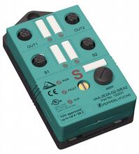
AS-Interface safety module VAA-2E2A-G2-S/EA2
- Addressing jack
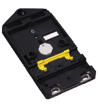
- Flat cable connection with cable piercing technique, variable flat cable guide
- Communication monitoring
- Power supply of outputs from the external auxiliary voltage
- 2 safe inputs for mechanical contacts such as EMERGENCY-STOP switch
- Power supply of inputs from the module
- Function display for bus, ext. auxiliary voltage, inputs and outputs
- Output overload monitoring
- Switchable internal logic operation of the inputs and outputs via parameter bit


Please note: All product-related documents, such as certificates, declarations of conformity, etc., which were issued prior to the conversion under the name Pepperl+Fuchs GmbH or Pepperl+Fuchs AG, also apply to Pepperl+Fuchs SE.
Descargue la hoja de datos completa en PDF:
Extracto de la hoja de datos: Información técnica del VAA-2E2A-G2-S/EA2
| Descripción del producto |
|---|
| G2 safety module 2 safety-related inputs and 2 conventional electronic outputs |
| General specifications | ||
|---|---|---|
| Node type | Safety-Slave | |
| AS-Interface specification | V2.1 | |
| Required master specification | ≥ V2.1 | |
| UL File Number | E87056 | |
| Functional safety related parameters | ||
| Safety Integrity Level (SIL) | SIL 3 | |
| MTTFd | 200 a | |
| Indicators/operating means | ||
| LED FAULT | error display; LED red red: communication error or address is 0 red flashing: Output supply overload |
|
| LED PWR | AS-Interface voltage; LED green | |
| LED AUX | ext. auxiliary voltage UAUX ; LED green | |
| LED IN | switching state (input); 2 LED yellow | |
| LED OUT | Switching state (output); 2 LED yellow | |
| Electrical specifications | ||
| Auxiliary voltage (output) | 24 V DC ± 15 % PELV | |
| Rated operating voltage | 26.5 ... 31.6 V from AS-Interface | |
| Rated operating current | ≤ 70 mA | |
| Protection class | III | |
| Input | ||
| Number/Type | 2 safety-related inputs for mechanical contacts, cross-circuit monitored: 2 single-channel contacts: up to category 2 in accordance with EN 954-1 or 1, 2-channel contact: up to category 4 in accordance with EN 954-1 Cable length must not exceed 30 m per input. |
|
| Supply | from AS-Interface | |
| Voltage | 20 ... 30 V DC pulsed | |
| Current loading capacity | input current limited ≤ 15 mA, overload and short-circuit resistant |
|
| Output | ||
| Number/Type | 2 conventional electronic outputs, PNP | |
| Supply | from external auxiliary voltage UAUX | |
| Voltage | ≥ (UAUX - 0.5 V) | |
| Current | 1 A per output | |
| Compliance with standards and directives | ||
| Directive conformity | ||
| EMC Directive 2004/108/EC | EN 61326, EN 50295, EN 61496-1 | |
| Standard conformity | ||
| Electromagnetic compatibility | EN 61000-6-2, EN 61000-4-5 1 kV asymmetric, criterion B, EN 61000-6-4 | |
| Emitted interference | EN 61000-6-4:2001 | |
| Insulation coordination | EN 50178:1998 | |
| Functional safety | EN 954-1:1996 (up to category 4), BIA Final Draft "Proposal for a principle to the verification and certification of field busses for transmission of safety related signals" 28.05.2000, IEC 61508 up to SIL3 | |
| Degree of protection | EN 60529:2000 | |
| Fieldbus standard | EN 50295:1999, IEC 62026-2:2006 | |
| Electrical safety | EN 50178:1998 , IEC 60204-1:2007 | |
| Standards | NFPA 79:2002 | |
| Programming instructions | ||
| Profile | S-7.B | |
| IO code | 7 | |
| ID code | B | |
| ID1 code | F | |
| ID2 code | 0 | |
| Data bits (function via AS-Interface) | ||
| D0 | ||
| D1 | ||
| D2 | ||
| D3 | ||
| Parameter bits (programmable via AS-i) | function | |
| P0 | Logic operation: P0 = 1 (default settings): The outputs are controlled via AS-Interface. P0 = 0: The outputs are controlled via AS-Interface or the inputs. The corresponding output is activated on opening the contacts of an input. |
|
| P1 | not used | |
| P2 | not used | |
| P3 | not used | |
| Ambient conditions | ||
| Ambient temperature | -25 ... 55 °C (-13 ... 131 °F) | |
| Storage temperature | -25 ... 85 °C (-13 ... 185 °F) | |
| Shock and impact resistance | 15 g, 11 ms in 6 spatial directions 3 shocks 10 g, 16 ms in 6 spatial directions 1000 shocks |
|
| Vibration resistance | 0.75 mm 10 ... 57 Hz , 5 g 57 ... 150 Hz, 20 cycles | |
| Mechanical specifications | ||
| Degree of protection | IP67 | |
| Connection | Cable piercing method flat cable yellow/flat cable black inputs/outputs: M12 round connector |
|
| Material | ||
| Housing | PBT | |
| Mass | 100 g | |
| Mounting | Mounting plate | |
Classifications
| System | Classcode |
|---|---|
| ECLASS 13.0 | 27272603 |
| ECLASS 12.0 | 27242604 |
| ECLASS 11.0 | 27242604 |
| ECLASS 10.0.1 | 27242604 |
| ECLASS 9.0 | 27242604 |
| ECLASS 8.0 | 27242604 |
| ECLASS 5.1 | 27242604 |
| ETIM 9.0 | EC001599 |
| ETIM 8.0 | EC001599 |
| ETIM 7.0 | EC001599 |
| ETIM 6.0 | EC001599 |
| ETIM 5.0 | EC001599 |
| UNSPSC 12.1 | 39121535 |
Details: VAA-2E2A-G2-S/EA2
Product Documentation: VAA-2E2A-G2-S/EA2
| Manuals | Idioma | Tipo de archivo | Tamaño |
|---|---|---|---|
| Instruction Manual VAA-2E2A-G2-S/EA2 | ENG | 1070 KB |
Design / Simulation: VAA-2E2A-G2-S/EA2
| CAD | Idioma | Tipo de archivo | Tamaño |
|---|---|---|---|
| CAD 3-D / CAD 3-D | ALL | STP | 149 KB |
Approvals: VAA-2E2A-G2-S/EA2
| Certificates | Número de Certificado | Idioma | Tipo de archivo | Tamaño |
|---|---|---|---|---|
| AS-Interface | 55601 | ALL | 230 KB | |
| TUV Rheinland Functional Safety | 968/EZ 151.01/03 | ALL | 38 KB |
Productos asociados: VAA-2E2A-G2-S/EA2
| Matching System Components | ||||||
|---|---|---|---|---|---|---|
|
||||||
| Accessories | ||||||
|
||||||
|
||||||

Conozca la gama completa de los productos AS-Interface.


Pepperl+Fuchs SE
Lilienthalstraße 200
68307 Mannheim
Germany
info@de.pepperl-fuchs.com
 +49 621 776-0
Pepperl + Fuchs es líder en el desarrollo y la fabricación de sensores electrónicos y componentes para el mercado de la automatización global. Su incesante innovación, calidad duradera y crecimiento constante garantizan el éxito continuado, desde hace más de 70 años. Pepperl + Fuchs emplea a 6.300 personas en todo el mundo y cuenta con fábricas en Alemania, EE.UU., Singapur, Hungría, Indonesia y Vietnam, la mayoría de ellas con certificado ISO 9001.