

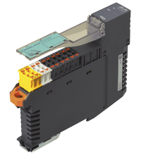
AS-Interface analog module VBA-2A-KE5-IL/UL
- Housing with push-in connection technology and mechanically coded terminal blocks
- Housing width 19 mm, installation in the switch cabinet on DIN mounting rail
- Power supply of outputs from the external auxiliary voltage
- Function display for bus, external auxiliary voltage and outputs


Please note: All product-related documents, such as certificates, declarations of conformity, etc., which were issued prior to the conversion under the name Pepperl+Fuchs GmbH or Pepperl+Fuchs AG, also apply to Pepperl+Fuchs SE.
Faça o download das folhas de dados em PDF:
Folhas de dados: Dados técnicos do VBA-2A-KE5-IL/UL
| Descrição do Produto |
|---|
| Switch cabinet module Two analog outputs |
| General specifications | ||
|---|---|---|
| Node type | Standard node | |
| AS-Interface specification | V3.0 | |
| Required gateway specification | ≥ V2.1 | |
| UL File Number | E223772 | |
| MTBF | 197 a | |
| Indicators/operating means | ||
| LED FAULT | Fault indication: red LED Red: communication error or address is 0 Red flashing: peripheral fault |
|
| LED PWR | AS-Interface voltage; green LED Green: voltage OK Flashing green: address 0 or peripheral error |
|
| LED AUX | ext. auxiliary voltage UAUX; dual LED green/red green: voltage OK red: reverse voltage |
|
| LED OUT | Status of output signal; yellow LED Yellow: output value within value range Continually on: current mode 1.4 s on/0.1 s off: voltage mode Flashing yellow: wire break (at current output) or output value outside of value range |
|
| Electrical specifications | ||
| Auxiliary voltage (output) | 24 V DC ± 15 % PELV | |
| Rated operating voltage | 26.5 ... 31.6 V from AS-Interface | |
| Rated operating current | ≤ 75 mA | |
| Protection class | III | |
| Current consumption | IAUX ≤ 650 mA | |
| Surge protection | UAUX, Ue: overvoltage category II, safe isolated power supplies (PELV) | |
| Output | ||
| Number/Type | Two analog outputs Current: 0 mA ... 20 mA Voltage: 0 V ... 10 V |
|
| Supply | From auxiliary voltage UAUX | |
| Load | voltage output: min. 1 kΩ current output: max. 600 Ω |
|
| Current loading capacity | ≤ 600 mA (signal current + actuator power supply) from external auxiliary voltage UAUX, overload-proof and short-circuit proof | |
| Resolution | Voltage output: 3 mV Current output: 6 µA |
|
| Accuracy | 0.15 % of full-scale value | |
| Temperature influence | 1 µA/K or 0,3 mV/K | |
| Short-circuit current | voltage output: max. 22 mA | |
| Directive conformity | ||
| Electromagnetic compatibility | ||
| Directive 2014/30/EU | EN 62026-2:2013 | |
| Standard conformity | ||
| Degree of protection | EN 60529:2000 | |
| Fieldbus standard | EN 62026-2:2013 | |
| Emitted interference | EN 61000-6-4:2007 | |
| AS-Interface | EN 62026-2:2013 | |
| Noise immunity | EN 61000-6-2:2005, EN 61326-1:2006, EN 62026-2:2013 | |
| Programming instructions | ||
| Profile | S-7.3.5 | |
| IO code | 7 | |
| ID code | 3 | |
| ID1 code | F | |
| ID2 code | 5 | |
| Data bits (function via AS-Interface) | The transfer of the data value is based on AS-Interface Profile 7.3. | |
| Parameter bits (programmable via AS-i) | function | |
| P0 | Watchdog: P0=1 (default), watchdog active P0=0, watchdog inactive |
|
| P1 | Output mode O1: P1=1 (default), current output P1=0, voltage output |
|
| P2 | Indication of peripheral fault: P2=1 (default), peripheral fault is reported P2=0, peripheral fault is not reported |
|
| P3 | Output mode O2: P3=1 (default), current output P3=0, voltage output |
|
| Ambient conditions | ||
| Ambient temperature | -25 ... 70 °C (-13 ... 158 °F) | |
| Storage temperature | -25 ... 85 °C (-13 ... 185 °F) | |
| Relative humidity | 85 % , noncondensing | |
| Climatic conditions | For indoor use only | |
| Altitude | ≤ 2000 m above MSL | |
| Shock and impact resistance | 15 g, 11 ms in 6 spatial directions, 3 shocks 10 g, 16 ms in 6 spatial directions, 1000 shocks | |
| Vibration resistance | 0.35 mm 10 ... 57 Hz , 5 g 57 ... 150 Hz, 20 cycles | |
| Pollution degree | 2 | |
| Mechanical specifications | ||
| Degree of protection | IP20 |
|
| Connection | Removable push-in terminals rated connection capacity: rigid: 0.20 mm2 ... 1.5 mm2 flexible (without wire end ferrule): 0.20 mm2 ... 2.5 mm2 flexible (with wire end ferrule): 0.25 mm2 ... 1.5 mm2 |
|
| Material | ||
| Housing | PA 66-FR | |
| Mass | 110 g | |
| Dimensions | ||
| Height | 100 mm | |
| Width | 18.9 mm | |
| Length | 124 mm | |
| Mounting | DIN mounting rail | |
| Note | Max. length of jumpers = 5 cm | |
Classifications
| System | Classcode |
|---|---|
| ECLASS 13.0 | 27242601 |
| ECLASS 12.0 | 27242601 |
| ECLASS 11.0 | 27242601 |
| ECLASS 10.0.1 | 27242601 |
| ECLASS 9.0 | 27242601 |
| ECLASS 8.0 | 27242601 |
| ECLASS 5.1 | 27242601 |
| ETIM 9.0 | EC001596 |
| ETIM 8.0 | EC001596 |
| ETIM 7.0 | EC001596 |
| ETIM 6.0 | EC001596 |
| ETIM 5.0 | EC001596 |
| UNSPSC 12.1 | 39121535 |
Details: VBA-2A-KE5-IL/UL
Product Documentation: VBA-2A-KE5-IL/UL
| Brief Instructions | Idioma | Tipo de Arquivo | Tamanho do Arquivo |
|---|---|---|---|
| Instruction leaflet / Beipackzettel | ALL | 133 KB | |
| Manuals | |||
| Manual | ENG | 1983 KB | |
Design / Simulation: VBA-2A-KE5-IL/UL
| CAD | Idioma | Tipo de Arquivo | Tamanho do Arquivo |
|---|---|---|---|
| CAD 3-D / CAD 3-D | ALL | STP | 19087 KB |
Approvals: VBA-2A-KE5-IL/UL
| Certificates | Número do Certificado | Idioma | Tipo de Arquivo | Tamanho do Arquivo |
|---|---|---|---|---|
| US CA UL | E223772 | ALL | LINK | --- |
| Worldwide AS-International Association AS-Interface | 129002 | ALL | 134 KB | |
| Declaration of Conformity | ||||
| EU Declaration of Conformity (P+F) / EU-Konformitäterklärung (P+F) | DOC-3534A | ALL | 108 KB | |
Produtos Relacionados: VBA-2A-KE5-IL/UL
| Accessories | ||||||
|---|---|---|---|---|---|---|
|
||||||
|
||||||
|
||||||


Este documento técnico gratuito em PDF compara os diferentes protocolos de comunicação baseados em TCP (AMQP, OPC UA, MQTT, REST API) que alcançaram muito sucesso e hoje são considerados os ativadores da Internet Industrial das Coisas e da Indústria 4.0. Faça o download gratuito agora mesmo!
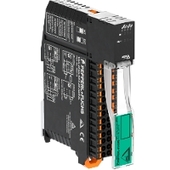
O design exclusivo do invólucro do novo módulo de gabinete do interruptor KE5 permite uma visibilidade distinta e simplifica a montagem, o cabeamento e a manutenção dentro dos gabinetes do interruptor e caixas de junção.
Conheça nossa linha completa de produtos Interface AS.


Pepperl+Fuchs Ltda.
Rua José Versolato, 111
Domo Corporate Tower, Conjunto 144
09750-730 São Bernardo do Campo, SP
Brasil
vendas@br.pepperl-fuchs.com
 +55 11 4007 1448
A Pepperl+Fuchs é líder na fabricação e no desenvolvimento de sensores e componentes eletrônicos para o setor global da automação industrial. Inovação contínua, qualidade e crescimento constante garantem o nosso sucesso há mais de 70 anos. Empregamos mais de 6.300 colaboradores em todo o mundo e contamos com fábricas próprias na Alemanha, Estados Unidos, Cingapura, Hungria, Indonésia e Vietnã, todas com certificação ISO 9001.