

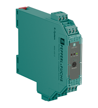
Universal Temperature Converter KFD2-UT2-2
- 2-channel signal conditioner
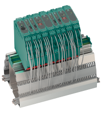
- 24 V DC supply (Power Rail)
- Thermocouple, RTD, potentiometer or voltage input
- Usable as signal splitter (1 input and 2 outputs)
- Current output 0/4 mA ... 20 mA
- Sink or source mode
- Configurable by PACTware
- Line fault (LFD) and sensor burnout detection
- Up to SIL 2 acc. to IEC/EN 61508 / IEC/EN 61511


Please note: All product-related documents, such as certificates, declarations of conformity, etc., which were issued prior to the conversion under the name Pepperl+Fuchs GmbH or Pepperl+Fuchs AG, also apply to Pepperl+Fuchs SE.
Scarica il Datasheet completo in formato PDF:
Estratto del Datasheet: Dati tecnici del KFD2-UT2-2
| General specifications | ||
|---|---|---|
| Signal type | Analog input | |
| Functional safety related parameters | ||
| Safety Integrity Level (SIL) | SIL 2 | |
| Supply | ||
| Connection | terminals 14+, 15- or power feed module/Power Rail | |
| Rated voltage | 20 ... 30 V DC | |
| Ripple | within the supply tolerance | |
| Power dissipation | ≤ 1.53 W | |
| Power consumption | max. 1.53 W | |
| Interface | ||
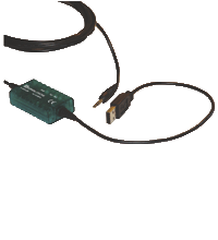
| Programming interface | programming socket | |
| Input | ||
| Connection side | field side | |
| Connection | terminals 1, 2, 3; 4, 5, 6 | |
| RTD | type Pt10, Pt50, Pt100, Pt500, Pt1000 (EN 60751: 1995) type Pt10GOST, Pt50GOST, Pt100GOST, Pt500GOST, Pt1000GOST (6651-94) type Cu10, Cu50, Cu100 (P50353-92) type Ni100 (DIN 43760) |
|
| Measuring current | approx. 200 µA with RTD | |
| Types of measuring | 2-, 3-wire connection | |
| Lead resistance | max. 50 Ω per line | |
| Measurement loop monitoring | sensor breakage, sensor short-circuit | |
| Thermocouples | type B, E, J, K, N, R, S, T (IEC 584-1: 1995) type L (DIN 43710: 1985) type TXK, TXKH, TXA (P8.585-2001) |
|
| Cold junction compensation | external and internal | |
| Measurement loop monitoring | sensor breakage | |
| Potentiometer | 0 ... 20 kΩ (2-wire connection), 0.8 ... 20 kΩ (3-wire connection) | |
| Voltage | selectable within the range -100 ... 100 mV | |
| Input resistance | ≥ 1 MΩ (-100 ... 100 mV) | |
| Output | ||
| Connection side | control side | |
| Connection | output I: terminal 7: source (-), sink (+), terminal 8: source (+), terminal 9: sink(-) output II: terminal 10: source (-), sink (+), terminal 11: source (+), terminal 12: sink(-) |
|
| Output I, II | Analog current output | |
| Current range | 0 ... 20 mA or 4 ... 20 mA | |
| Fault signal | downscale 0 or 2 mA, upscale 21.5 mA (acc. NAMUR NE43) | |
| Source | load 0 ... 550 Ω open-circuit voltage ≤ 18 V |
|
| Sink | Voltage across terminals 5 ... 30 V. If the current is supplied from a source > 16.5 V, series resistance of ≥ (V - 16.5)/0.0215 Ω is needed, where V is the source voltage. The maximum value of the resistance is (V - 5)/0.0215 Ω. |
|
| Transfer characteristics | ||
| Deviation | ||
| After calibration | Pt100: ± (0.06 % of measurement value in K + 0.1 % of span + 0.1 K (4-wire connection)) thermocouple: ± (0.05 % of measurement value in °C + 0.1 % of span + 1 K (1.2 K for types R and S)) , includes ± 0.8 K fault of the cold junction compensation (CJC) mV: ± (50 µV + 0.1 % of span) potentiometer: ± (0.05 % of full scale + 0.1 % of span, (excludes faults due to lead resistance)) |
|
| Influence of ambient temperature | Pt100: ± (0.0015 % of measurement value in K + 0.006 % of span)/K ΔTamb*) thermocouple: ± (0.02 K + 0.005 % of measurement value in °C + 0.006 % of span)/K ΔTamb*)), influence of cold junction compensation (CJC) included mV: ± (0.01 % of measurement value + 0.006 % of span)/K ΔTamb*) potentiometer: ± 0.006 % of span/K ΔTamb*) *) ΔTamb = ambient temperature change referenced to 23 °C (296 K) |
|
| Influence of supply voltage | < 0.01 % of span | |
| Influence of load | ≤ 0.001 % of output value per 100 Ω | |
| Reaction time | worst case value (sensor breakage and/or sensor short circuit detection enabled) mV: 1.2 s, thermocouples with CJC: 1.4 s, thermocouples with fixed ref. temp: 1.4 s, 3- or 4-wire RTD: 1.1 s, 2-wire RTD: 920 ms, Potentiometer: 3-wire connection 2.8 s, 2-wire connection 2.25 s |
|
| Galvanic isolation | ||
| Input/Other circuits | basic insulation according to IEC 61010-1, rated insulation voltage 300 Veff | |
| Output/supply, programming input | functional insulation, rated insulation voltage 50 V AC There is no electrical isolation between the programming input and the supply. The programming cable provides galvanic isolation so that ground loops are avoided. |
|
| Indicators/settings | ||
| Display elements | LEDs | |
| Configuration | via PACTware | |
| Labeling | space for labeling at the front | |
| Directive conformity | ||
| Electromagnetic compatibility | ||
| Directive 2014/30/EU | EN 61326-1:2013 (industrial locations) | |
| Conformity | ||
| Electromagnetic compatibility | NE 21:2006 | |
| Degree of protection | IEC 60529:2001 | |
| Ambient conditions | ||
| Ambient temperature | -20 ... 60 °C (-4 ... 140 °F) | |
| Mechanical specifications | ||
| Degree of protection | IP20 | |
| Connection | screw terminals | |
| Mass | approx. 130 g | |
| Dimensions | 20 x 119 x 115 mm (0.8 x 4.7 x 4.5 inch) (W x H x D) , housing type B2 | |
| Height | 119 mm | |
| Width | 20 mm | |
| Depth | 115 mm | |
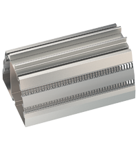
| Mounting | on 35 mm DIN mounting rail acc. to EN 60715:2001 | |
| General information | ||
| Supplementary information | Observe the certificates, declarations of conformity, instruction manuals, and manuals where applicable. For information see www.pepperl-fuchs.com. | |
Classifications
| System | Classcode |
|---|---|
| ECLASS 13.0 | 27210129 |
| ECLASS 12.0 | 27210129 |
| ECLASS 11.0 | 27210129 |
| ECLASS 10.0.1 | 27210129 |
| ECLASS 9.0 | 27210129 |
| ECLASS 8.0 | 27210190 |
| ECLASS 5.1 | 27210107 |
| ETIM 9.0 | EC002919 |
| ETIM 8.0 | EC002919 |
| ETIM 7.0 | EC002919 |
| ETIM 6.0 | EC002919 |
| ETIM 5.0 | EC001485 |
| UNSPSC 12.1 | 32101514 |
Details: KFD2-UT2-2
Informative Literature: KFD2-UT2-2
| Literature | Lingua | File tipo | Dimensioni |
|---|---|---|---|
| Application Report - Generating Electricity in Coal-Fired Power Plants | ENG | 412 KB | |
| Application Report - Reliable Signal Conversion at High Ambient Temperatures | ENG | 291 KB | |
| Application Report - Screening Systems in Sewage Treatment Plants | ENG | 577 KB |
Product Documentation: KFD2-UT2-2
| Safety and Security Documentation | Lingua | File tipo | Dimensioni |
|---|---|---|---|
| Manuale di istruzioni | ITA | 77 KB | |
| Functional Safety Manual | ENG | 1486 KB | |
| Manuals | |||
| Manual KF**-UT2-(Ex)*(-1) | ENG | 1682 KB | |
| System Manual | ENG | 3694 KB | |
| Installation and configuration guide Device Type Manager (DTM) | ENG | 8665 KB | |
Design / Simulation: KFD2-UT2-2
| CAD | Lingua | File tipo | Dimensioni |
|---|---|---|---|
| CAD 3-D / CAD 3-D | ALL | STP | 2510 KB |
| CAD Portal / CAD Portal | ALL | LINK | --- |
| CAE | |||
| CAE EPLAN Data Portal / CAE EPLAN Data Portal | ALL | LINK | --- |
| CAE EPLAN macro EDZ / CAE EPLAN Makro EDZ | ALL | EDZ | 1509 KB |
Approvals: KFD2-UT2-2
| Certificates | Certificato Numero | Lingua | File tipo | Dimensioni |
|---|---|---|---|---|
| DNV Marine | TAA00001WX | ALL | 106 KB | |
| exida Functional Safety Assessment | P+F 05/03-24 R023 | ALL | 437 KB |
Software: KFD2-UT2-2
| Frameworks | informazioni sulla liberatoria | File tipo | Dimensioni |
|---|---|---|---|
| PACTware 4.1 SP6 / PACTware 4.1 SP6 | 4.1.0.53 | ZIP | 43327 KB |
| PACTware 5.0 / PACTware 5.0 | 5.0.5.31 | ZIP | 44203 KB |
| Device Description Files/Drivers | |||
| DTM Collection Interface Technology 2 / DTM Collection Interface Technology 2 | 1.4.110.76 | ZIP | 32633 KB |
Prodotti associati : KFD2-UT2-2
| Matching System Components | ||||||
|---|---|---|---|---|---|---|
|
||||||
|
||||||
|
||||||
|
||||||
|
||||||
|
||||||
|
||||||
|
||||||
|
||||||
| Accessories | ||||||
|
||||||
|
||||||
|
||||||
|
||||||
|
||||||


Choose from various selection criteria like safety integrity level, performance level, device function, and signal type and find the SIL/PL assessed device that you are looking for.


Pepperl+Fuchs FA Italia Srl
Via Ornago 24
20882 Bellusco (MB)
Italia
P.IVA 05970540968
infofa@it.pepperl-fuchs.com
 +39 039 69599 1
Pepperl+Fuchs srl
Via delle Arti e Mestieri, 4
20884 Sulbiate (MB)
Italia
P.IVA 02181770963
pa-info@it.pepperl-fuchs.com
+39 039 62921
Pepperl+Fuchs è leader mondiale nella tecnologia e nella produzione di sensori industriali e componenti elettronici per il mercato dell'automazione globale. Innovazione, crescita e qualità costante ne garantiscono il successo da oltre 70 anni. Pepperl+Fuchs impiega circa 6,300 persone in tutto il mondo ed ha siti produttivi a norma ISO 9001 in Germania, Stati Uniti, Singapore, Ungheria, Indonesia e Vietnam.