

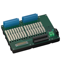
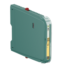
Termination Board HiCTB16-TRX-RAS-PL-IO16
- System board for Schneider Electric, Tricon CX series by Triconex
- For 16-channel universal I/O card 3902(A)X
- For 16 modules
- Recommended modules: HiC2027 (AI), HiC2027ES (AI), HiC2821 (DI), HiC2831R4 (DI), HiC2841 (DI), HiC2853R4 (DI)
- 24 V DC supply
- Hazardous area: pluggable screw terminals, blue
- Non-hazardous area: screw terminals, black
- Non-hazardous area: Sub-D connector (male), 50-pin
- Up to SIL 3 acc. to IEC/EN 61508


Please note: All product-related documents, such as certificates, declarations of conformity, etc., which were issued prior to the conversion under the name Pepperl+Fuchs GmbH or Pepperl+Fuchs AG, also apply to Pepperl+Fuchs SE.
Scarica il Datasheet completo in formato PDF:
Estratto del Datasheet: Dati tecnici del HiCTB16-TRX-RAS-PL-IO16
| Functional safety related parameters | ||
|---|---|---|
| Safety Integrity Level (SIL) | SIL 3 | |
| Systematic capability (SC) | SC 3 | |
| Supply | ||
| Connection | X20: terminals 3, 5(+); 4, 6(-) | |
| Nominal voltage | 24 V DC , in consideration of rated voltage of used isolators | |
| Voltage drop | 0.9 V , voltage drop across the series diode on the termination board must be considered | |
| Ripple | ≤ 10 % | |
| Fusing | 4 A , in each case for 16 modules | |
| Power dissipation | ≤ 500 mW , without modules | |
| Reverse polarity protection | yes | |
| Redundancy | ||
| Supply | Redundancy available. The supply for the isolators is decoupled, monitored and fused. | |
| Fault indication output | ||
| Connection | X20: terminals 1(+), 2(-) | |
| Output type | volt-free transistor output , not short-circuit protected , not overload protected | |
| Rated voltage | 30 V DC | |
| Rated current | 100 mA | |
| Signal level | no fault: (external voltage) - 1 V max. for 100 mA (Tamb = 25 °C (77 °F)) power supply fault/module fault: blocked output (off-state current ≤ 10 µA) |
|
| Indicators/settings | ||
| Display elements | LED PWR1 (termination board power supply), green LED LED PWR2 (termination board power supply), green LED |
|
| Directive conformity | ||
| Electromagnetic compatibility | ||
| Directive 2014/30/EU | EN 61326-1:2013 (industrial locations) | |
| Conformity | ||
| Electromagnetic compatibility | EN IEC 61326-3-2:2018 , NE 21:2017 For further information see system description. |
|
| Degree of protection | IEC 60529:2001 | |
| Ambient conditions | ||
| Ambient temperature | -20 ... 60 °C (-4 ... 140 °F) | |
| Storage temperature | -40 ... 85 °C (-40 ... 185 °F) | |
| Mechanical specifications | ||
| Degree of protection | IP20 | |
| Connection | ||
| Field side | explosion hazardous area: pluggable screw terminals , blue | |
| Control side | non-explosion hazardous area: output I: 50-pin Sub-D connector output II: screw terminals , black |
|
| Supply | pluggable screw terminals , black | |
| Fault output | pluggable screw terminals , black | |
| Core cross section | screw terminals 0.25 ... 2.5 mm2 (24 ... 12 AWG) | |
| Material | housing: polycarbonate, 10 % glass fiber reinforced | |
| Mass | approx. 935 g | |
| Dimensions | 266 x 200 x 163 mm (10.5 x 7.9 x 6.42 inch) (W x H x D) , depth including module assembly | |
| Height | 200 mm | |
| Width | 266 mm | |
| Depth | 163 mm | |
| Mounting | on 35 mm DIN mounting rail acc. to EN 60715:2001 | |
| Data for application in connection with hazardous areas | ||
| EU-type examination certificate | CESI 06 ATEX 022 | |
| Marking |  II (1)G [Ex ia Ga] IIC II (1)D [Ex ia Da] IIIC I (M1) [Ex ia Ma] I II (1)G [Ex ia Ga] IIC II (1)D [Ex ia Da] IIIC I (M1) [Ex ia Ma] I |
|
| Non-hazardous area | ||
| Maximum safe voltage | 250 V (Attention! Um is no rated voltage.) | |
| Galvanic isolation | ||
| Field circuit/control circuit | safe electrical isolation acc. to IEC/EN 60079-11, voltage peak value 375 V | |
| Directive conformity | ||
| Directive 2014/34/EU | EN IEC 60079-0:2018+AC:2020 , EN 60079-11:2012 , EN 50303:2000 | |
| International approvals | ||
| UL approval | E106378 | |
| Control drawing | 116-0327 | |
| IECEx approval | ||
| IECEx certificate | IECEx CES 06.0003 | |
| IECEx marking | [Ex ia Ga] IIC [Ex ia Da] IIIC [Ex ia Ma] I |
|
| General information | ||
| Supplementary information | Observe the certificates, declarations of conformity, instruction manuals, and manuals where applicable. For information see www.pepperl-fuchs.com. | |
Classifications
| System | Classcode |
|---|---|
| ECLASS 13.0 | 27210107 |
| ECLASS 12.0 | 27210107 |
| ECLASS 11.0 | 27210107 |
| ECLASS 10.0.1 | 27210107 |
| ECLASS 9.0 | 27210107 |
| ECLASS 8.0 | 27210107 |
| ECLASS 5.1 | 27210121 |
| ETIM 9.0 | EC001485 |
| ETIM 8.0 | EC001485 |
| ETIM 7.0 | EC001485 |
| ETIM 6.0 | EC001485 |
| ETIM 5.0 | EC001485 |
| UNSPSC 12.1 | 39121008 |
Details: HiCTB16-TRX-RAS-PL-IO16
Product Documentation: HiCTB16-TRX-RAS-PL-IO16
| Product information | Lingua | File tipo | Dimensioni |
|---|---|---|---|
| Pinout table Triconex HiCTB16-TRX-RAS-PL-IO16 | ENG | 138 KB | |
| Brief Instructions | |||
| Brief instructions | ENG | 3237 KB | |
| Manufacturer declaration Functional Safety | ENG | 171 KB | |
| Safety and Security Documentation | |||
| Manuale di istruzioni | ITA | 157 KB | |
| Manuals | |||
| System Manual | ENG | 5438 KB | |
Approvals: HiCTB16-TRX-RAS-PL-IO16
| Certificates | Certificato Numero | Lingua | File tipo | Dimensioni |
|---|---|---|---|---|
| Brasil TUV Rheinland Brazil | TÜV 14.0084 X | ALL | 1284 KB | |
| CESI IECEx Certificate of Conformity | IECEx CES 06.0003 | ALL | LINK | --- |
| China SITIIAS CCC Ex Certificate | 2021322308004238 (Singapore) | ALL | 1842 KB | |
| Europe CESI ATEX Category (1) GD ATEX Category (M1) | CESI 06 ATEX 022 | ALL | 869 KB | |
| India PESO (India) CCOE | A/P/HQ/KA/104/5881 (P508977) | ALL | 100 KB | |
| USA Canada UL Hazardous Location Certificate of Compliance cULus UL E106378 | CoC E106378 RepRef E106378-20100930 | ALL | 478 KB | |
| Control Drawings | ||||
| Control drawing UL / Control drawing UL | ALL | 166 KB | ||
| Declaration of Conformity | ||||
| EU Declaration of Conformity (P+F) | TDOC-4840BITA | ITA | 180 KB | |
Prodotti associati : HiCTB16-TRX-RAS-PL-IO16
| Accessories | ||||||
|---|---|---|---|---|---|---|
|
||||||
|
||||||
|
||||||
|
||||||
|
||||||


Pepperl+Fuchs FA Italia Srl
Via Ornago 24
20882 Bellusco (MB)
Italia
P.IVA 05970540968
infofa@it.pepperl-fuchs.com
 +39 039 69599 1
Pepperl+Fuchs srl
Via delle Arti e Mestieri, 4
20884 Sulbiate (MB)
Italia
P.IVA 02181770963
pa-info@it.pepperl-fuchs.com
+39 039 62921
Pepperl+Fuchs è leader mondiale nella tecnologia e nella produzione di sensori industriali e componenti elettronici per il mercato dell'automazione globale. Innovazione, crescita e qualità costante ne garantiscono il successo da oltre 70 anni. Pepperl+Fuchs impiega circa 6,300 persone in tutto il mondo ed ha siti produttivi a norma ISO 9001 in Germania, Stati Uniti, Singapore, Ungheria, Indonesia e Vietnam.