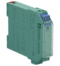
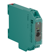
Voltage Repeater KFD2-VR-Ex1.19-Y109129
- 1-channel isolated barrier
- 24 V DC supply (Power Rail)
- Voltage input -10 V ... 10 V
- Transmission frequency up to 50 kHz
- Voltage output -10 V ... 10 V
Please note: All product-related documents, such as certificates, declarations of conformity, etc., which were issued prior to the conversion under the name Pepperl+Fuchs GmbH or Pepperl+Fuchs AG, also apply to Pepperl+Fuchs SE.
Pobierz pełną kartę katalogową w formie pliku PDF:
Dane techniczne KFD2-VR-Ex1.19-Y109129
| General specifications | ||
|---|---|---|
| Signal type | Analog input | |
| Supply | ||
| Connection | Power Rail or terminals 11+, 12- | |
| Rated voltage | 20 ... 35 V DC | |
| Ripple | within the supply tolerance | |
| Rated current | < 30 mA | |
| Input | ||
| Connection side | field side | |
| Connection | terminals 4+, 5- | |
| Input resistance | min. 10 MΩ | |
| Transmission range | -10 ... 10 V | |
| Offset voltage/current | < 10 mV / < 1 µA | |
| Output | ||
| Connection side | control side | |
| Connection | terminals 7-, 8+ | |
| Voltage | -10 ... 10 V | |
| Output resistance | max. 20 Ω | |
| Transfer characteristics | ||
| Cut-off frequency | 50 kHz (-3 dB) | |
| Deviation | ||
| After calibration | ± 30 mV at 20 °C (68 °F) | |
| Influence of ambient temperature | < 0.01 % of span per K | |
| Rise time | ≤ 10 µs | |
| Galvanic isolation | ||
| Output/power supply | functional insulation, rated insulation voltage 50 V AC | |
| Indicators/settings | ||
| Display elements | LED | |
| Labeling | space for labeling at the front | |
| Directive conformity | ||
| Electromagnetic compatibility | ||
| Directive 2014/30/EU | EN 61326-1:2013 (industrial locations) | |
| Conformity | ||
| Electromagnetic compatibility | NE 21 | |
| Degree of protection | IEC 60529 | |
| Ambient conditions | ||
| Ambient temperature | -20 ... 60 °C (-4 ... 140 °F) | |
| Mechanical specifications | ||
| Degree of protection | IP20 | |
| Connection | screw terminals | |
| Mass | approx. 110 g | |
| Dimensions | 20 x 107 x 115 mm (0.8 x 4.2 x 4.5 inch) (W x H x D) , housing type B1 | |
| Height | 100 mm | |
| Width | 20 mm | |
| Depth | 115 mm | |
| Mounting | on 35 mm DIN mounting rail acc. to EN 60715:2001 | |
| Data for application in connection with hazardous areas | ||
| EU-type examination certificate | BAS 01 ATEX 7262 | |
| Marking |  II (1)GD, I (M1) [Ex ia Ga] IIC, [Ex ia Da] IIIC, [Ex ia Ma] I (-20 °C ≤ Tamb ≤ 60 °C) , [circuit(s) in zone 0/1/2] II (1)GD, I (M1) [Ex ia Ga] IIC, [Ex ia Da] IIIC, [Ex ia Ma] I (-20 °C ≤ Tamb ≤ 60 °C) , [circuit(s) in zone 0/1/2] |
|
| Voltage | 15.5 V | |
| Current | 7.2 mA | |
| Power | 28 mW | |
| Supply | ||
| Maximum safe voltage | 250 V (Attention! The rated voltage is lower.) | |
| Output | ||
| Maximum safe voltage | 250 V (Attention! The rated voltage is lower.) | |
| Certificate | BASEEFA 10 ATEX 0079X | |
| Marking |  II 3G Ex ec IIC T4 Gc [device in zone 2] II 3G Ex ec IIC T4 Gc [device in zone 2] |
|
| Galvanic isolation | ||
| Input/Output | safe electrical isolation acc. to IEC/EN 60079-11, voltage peak value 375 V | |
| Input/power supply | safe electrical isolation acc. to IEC/EN 60079-11, voltage peak value 375 V | |
| Directive conformity | ||
| Directive 2014/34/EU | EN 60079-0:2012+A11:2013 , EN 60079-11:2012 , EN 60079-7:2015+A1:2018 | |
| International approvals | ||
| FM approval | ||
| Control drawing | 116-0129 | |
| UL approval | ||
| Control drawing | 116-0173 (cULus) | |
| CSA approval | ||
| Control drawing | 116-0132 | |
| IECEx approval | ||
| IECEx certificate | IECEx BAS 10.0040X | |
| IECEx marking | Ex ec IIC T4 Gc | |
| General information | ||
| Supplementary information | Observe the certificates, declarations of conformity, instruction manuals, and manuals where applicable. For information see www.pepperl-fuchs.com. | |
Classifications
| System | Classcode |
|---|---|
| ECLASS 13.0 | 27210125 |
| ECLASS 12.0 | 27210120 |
| ECLASS 11.0 | 27210120 |
| ECLASS 10.0.1 | 27210120 |
| ECLASS 9.0 | 27210120 |
| ECLASS 8.0 | 27210120 |
| ECLASS 5.1 | 27210120 |
| ETIM 9.0 | EC002653 |
| ETIM 8.0 | EC002653 |
| ETIM 7.0 | EC002653 |
| ETIM 6.0 | EC002653 |
| ETIM 5.0 | EC001485 |
| UNSPSC 12.1 | 32101514 |
Details: KFD2-VR-Ex1.19-Y109129
Function
This isolated barrier is used for intrinsic safety applications. It transfers voltage signals from hazardous areas to safe areas.
The input voltage of the terminals 4 and 5 is transferred to the terminals 7 and 8. The terminals 4 and 8 have the same polarity.
It repeats voltage signals from magnetic pickups, transducers, and flow meters between -10 V... 10 V.
This barrier is designed for frequencies up to 50 kHz.
Informative Literature: KFD2-VR-Ex1.19-Y109129
| Literature | Język | Typ pliku | Rozmiar pliku |
|---|---|---|---|
| Application Report - Energy Generation in Wastwater Treatment Plants | ENG | 532 KB | |
| Application Report - Generating Electricity in Coal-Fired Power Plants | ENG | 412 KB | |
| Application Report - Screening Systems in Sewage Treatment Plants | ENG | 577 KB | |
| Application Report - Sicherer Brennstofftransport in Kohlekraftwerken | ENG | 391 KB | |
| Application Report - Water Inlet in Wastewater Treatment Plants | ENG | 526 KB |
Product Documentation: KFD2-VR-Ex1.19-Y109129
| Safety and Security Documentation | Język | Typ pliku | Rozmiar pliku |
|---|---|---|---|
| Instrukcja obsługi | POL | 72 KB | |
| Manuals | |||
| Manual | ENG | 3685 KB | |
Design / Simulation: KFD2-VR-Ex1.19-Y109129
| CAD | Język | Typ pliku | Rozmiar pliku |
|---|---|---|---|
| CAD 3-D / CAD 3-D | ALL | STP | 105 KB |
| CAD Portal / CAD Portal | ALL | LINK | --- |
| CAE | |||
| EPLAN macro EDZ / EPLAN Makro EDZ | ALL | EDZ | 55 KB |
Approvals: KFD2-VR-Ex1.19-Y109129
| Certificates | Nr. certyfikatu | Język | Typ pliku | Rozmiar pliku |
|---|---|---|---|---|
| Baseefa Ex ec IECEx Certificate of Conformity | IECEx BAS 10.0040X | ALL | LINK | --- |
| Canada UL cUL | E106378 cUL (QUZW7) | ALL | LINK | --- |
| Europe Baseefa II (1) D I (M1) II (1) G | BAS 01 ATEX 7262 | ALL | 2608 KB | |
| Europe Baseefa II 3 G | Baseefa 10 ATEX 0079X | ALL | 2069 KB | |
| USA Canada UL Hazardous Location Certificate of Compliance cULus UL E106378 | CoC 20140902 - E106378 RepRef 20011030 | ALL | 429 KB | |
| USA FM | CoC 1Z2A1.AX | ALL | 78 KB | |
| USA UL | E106378 UL (QUZW) | ALL | LINK | --- |
| United Kingdom CML UK-Type Examination Certificate UKEX Category (1) D UKEX Category (1) G UKEX Category (M1) | CML 21UKEX2897 | ALL | 168 KB | |
| Control Drawings | ||||
| Control drawing UL / Control drawing UL | ALL | 1092 KB | ||
| Control drawing FM / Control drawing FM | ALL | 58 KB | ||
| Declaration of Conformity | ||||
| EU Declaration of Conformity (P+F) / EU-Konformitäterklärung (P+F) | DOC-0054C | ALL | 54 KB | |
Produkty powiązane: KFD2-VR-Ex1.19-Y109129
| Matching System Components | ||||||
|---|---|---|---|---|---|---|
|
||||||
|
||||||
|
||||||
|
||||||
|
||||||
|
||||||
| Accessories | ||||||
|
||||||
|
||||||
|
||||||




 +48 22 256 9770