

Machine-Readable Identification
Machine readable labels in electronic circuit board assembly with Data Matrix ECC 200
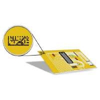
Data Matrix codes shown on an electronic circuit board
Introduction
As in practically all production processes, the question of unique product identification and tracking raises itself in the assembly of electronic circuit boards. The labels used for this have to be recorded in automated on-line systems. Until today, we have used barcodes like Code 39 or Code 128. The technical development and quality management requirements lead almost unavoidably to tendencies which we are able to list below:
- The amount of data increases because more products with various finishing processes have to be tracked
- The circuit boards get smaller and the density of the fitting higher
- Space available for coding becomes smaller
- The costs of the label have to be lowered
In particular, the first three points necessitate a method of labeling with substantially higher information density. The development of two dimensional codes (2D codes) which started at the end of the 1980’s in the USA, created possibilities in this area which enabled the ”Squaring of the circle” as well as the fulfillment of all four requirements to seem a realistic goal.
Standards create clarity and reliability
In the 1990’s, creativity knew no bounds, and over thirty different symbologies were in existence. At the same time, the realization dawned that neither the user nor the producer of the essential technical equipment, (printers, reading equipment, software etc.) would be able to cope with this great variety. In order to create clarity and reliability, standardization committees undertook the creation of a ”Norm” among these 2D symbologies. Since about two years ago, no more national activities in this field have taken place - everything is dealt with and focused upon the three work groups of the International Standardization Organization (ISO/IEC JTC 1/SC3, WG 1-3). Substantial ground work created national work groups like for example the Norm-committee of Information techniques N1 31 in DIN (Germany).
From bar to dot – Data Matrix ECC 200!
One of the leading codes is definitely Data Matrix. Today, this symbology is the first choice for the machine-readable label on small parts. Not only is the publication of DIS 16022 (Draft International Standard) imminent, but in the meantime, diverse organizations have declared their recommendation of Data Matrix (Automotive Industry Action Group AIAG, Electronics Industry Association EIA, SEMI and EDIFICE).
The advantages of Data Matrix are obvious:
- The highest data density = smaller space-requirement
- Virtually any symbol size (scalability) allows adaptation for various uses
- Suitable for nearly all printing processes (from off-Set through to Thermo-Transfer to direct marking by Inkjet or Laser)
- Readability even with low contrasts
- Readability in 360 degree orientation without special equipment
- Alphanumeric and thus customer-specific data settings are encodable
- Possibility of electronic data transfer
- High reading reliability due to automatic error-detection and -correction
It is especially this high flexibility combined with the extremely small space requirement which have attracted the interest of many electronics producers. In this field two processes compete with each other for the creation of the code, namely the labeling and direct inscribing processes (with Inkjet and Laser).
One question remains = to label or to inscribe directly?
For a long time, the label was the code carrier to be used. However, the structure of the Data Matrix (i.e. the structure in the form of individual cells) also made the implementation of the direct marking process the obvious choice. The implementation of inscription with inkjet printers and lasers engraving are exemplary here. Both processes clearly have advantages and disadvantages. The substantial arguments have been listed in the following table. The diagram opposite shows that the Thermo-transfer printing onto a label poses no direct problem; however, it incurs a larger space requirement and higher costs. With Inkjet direct printing and laser engraving, there are a number of conditions to take into consideration which are decisive in the practical success or failure.
| Thermo-Transfer | Inkjet | Laser Engraving | |
|
Printing Quality a - Symbol proportion |
good to very good |
limited |
good |
| b - Contrast | good to very good | depends on the background i.e. the undercoat |
depends on the material i.e. the process |
| Amount of data | flexible | restricted | restricted |
| Positioning | flexible as long as independent of | depends on the undercoat | depends on the undercoat |
| Space requirements | depends on the size of the lable | small | small |
| Costs | cost of lables | low | low |
The ”Norm” or not the ”Norm” - that is the question!
In its graphic depiction, the Data Matrix code is made from 3 parts, each of which have a specific function.
Finder Pattern
Defines the spatial position of the codes and the total size, and permits the recognition of possible distortion.
Dictates the density of the data cells inside the Code-matrix.
Data Region
Contains the data, provides a error-correction process which recognises faults within certain limitations and eliminates them.
The Finder Pattern and the Alternating Pattern are first and foremost determined by their function. If problems occur here, the code cannot be read. If one follows the standard requirements, the L-shape of the Finder Pattern must be made from two connected straight lines with well-defined edges and defined width. The Alternating Pattern should be made from discrete cells which are arranged in the 50-50 grid (from empty space to cell).
Maintaining the minimum requirement as a guarantee for success
The inkjet printing should be shown as the following, as examples of what deviation can occur in practice.
Disconnections - edges are made from semi-circular elements which do not lie on a straight line.
The individual dots create a wave, some individual dots are completely missing.
Data Region
The individual cells clearly deviate from the center of the grid. There is no longer any logic to their arrangement in the positions exactly in the middle between two central points. It initiates the error-correction.
Improved evaluation methods have ensured that Data Matrix symbols are generated in such a way can be read. However, it is noteworthy that the error-correction ensures readability and reading-reliability even when the codes are impaired by dirt from outside or cleaning. But a good proportion of this backup is needed; in order to be able to decode a symbol, one definitely must improve the reading equipment in the process. That is why the minimum requirements which guarantee the preservation of a function backup should be defined.
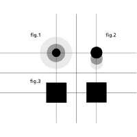
The diagram opposite depicts the problem. It concerns the area which accommodates a cell. If this area is too small, it will fall short of the sensor detection. If it is too big, then a neighbouring cell may be put as ”1”. In both cases, a substitution error occurs.
In Figure 2, we see the ”migration” of a code dot from the center. In an extreme case, the point lies exactly in the middle between two centers. After this, it is no longer possible to arrange this dot logically in a specific position in the Matrix.
The quadratic cells sketched underneath (Figure 3) are typical and ideal. We take this model as a reference. If the cell appears as a dot instead of a quadrat (square), then as a rule, the area is smaller. If the dots have a diameter the same as the length of the quadrat’s edges, then the area is about 20% smaller. This can be tolerated. As regards the ”migration” from the centre, a maximum value of 25% should not be exceeded. After this, in view of all the other tolerances, a logically correct arrangement can no longer be guaranteed. The drawing up of Symbol Print Quality Guidelines on this topic is in progress at the ISO Workgroup SC 31 WG 3. Up to the end of 1999, concrete suggestions should be formulated.


Pepperl+Fuchs Kereskedelmi Kft.
8200 Veszprém
Kistó utca 16 - 18.
Magyarország
sales@hu.pepperl-fuchs.com
 +36 88 545 902
A Pepperl+Fuchs az elektronikai érzékelők és alkatrészek vezető fejlesztő és gyártó vállalata a globális automatizálási piacon. A folyamatos innováció, a tartós minőség és az állandó növekedés már több mint 70 éve garantálja a sikert. A Pepperl+Fuchs 6300 embert alkalmaz világszerte, gyártóegységei vannak Németországban, az USA-ban, Szingapúrban, Magyarországon, Indonéziában és Vietnámban, legtöbbjük ISO 9001 tanusítvánnyal is rendelkezik.